Fast Supply Solutions
We match your technical product needs with the right manufacturers and quickly organize the process for competitive prices and short delivery times.

Cable-tray capacity is determined by evaluating cable weight, tray width, profile, sheet thickness, joint design and support spacing together. As support spacing increases, deflection rises and the same tray may carry a lower safe load.
Cable-tray capacity is determined by evaluating cable weight, tray width, profile, sheet thickness, joint design and support spacing together. As support spacing increases, deflection rises and the same tray may carry a lower safe load.
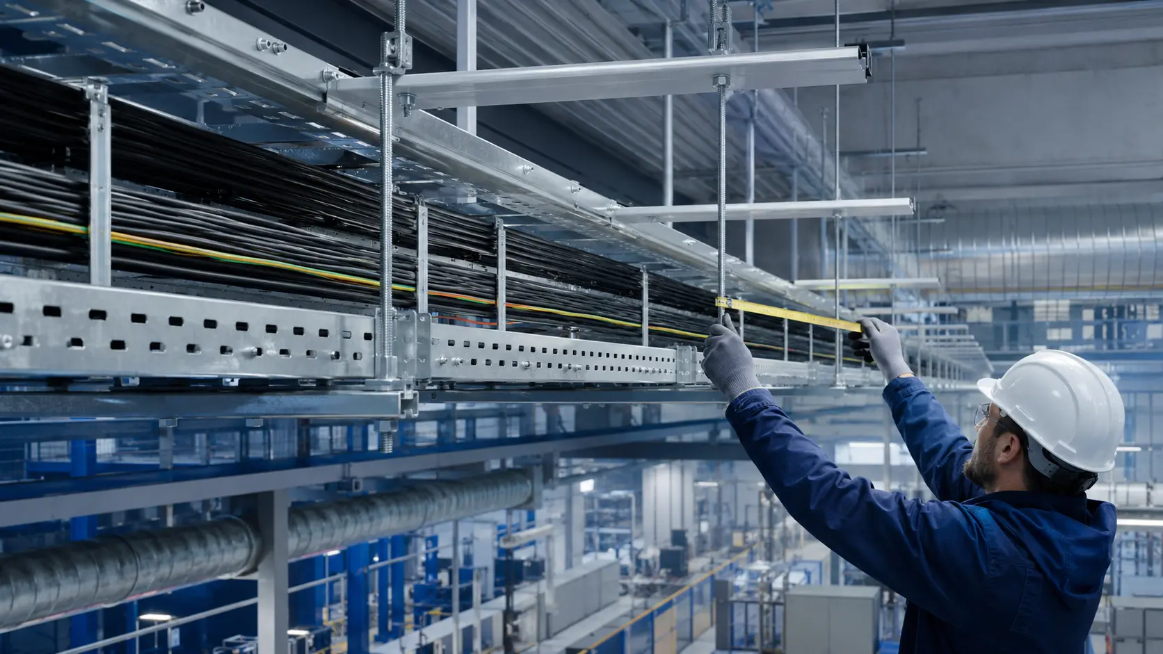
Calculate the mass per metre of every cable and add the tray, cover, divider and fittings. A suitable allowance should be included for future cable additions defined by the project.
A longer span increases tray deflection. Capacity must be checked against the manufacturer's load table for the selected span, not by sheet thickness alone. Joints and fittings should be located near supports where practical.
The tray should not be packed completely. Space is required for heat dissipation, installation, maintenance and future expansion. Power, control and data cables should be separated where the project requires it.
| Parameter | Check |
|---|---|
| Cable load | Total kg/m |
| Support spacing | Span in the manufacturer's load table |
| Fill | Cable area and ventilation allowance |
| Environment | Corrosion and temperature |
No. Profile geometry, tray width, joints and tested load data also determine capacity.
It is not recommended; space is needed for ventilation, installation, maintenance and expansion.
Yes. Covers, dividers and accessories must be included in the support-system load.
Specify the tray or ladder type, width and height, material and finish, total length, cable load, support spacing, fittings, project standard and delivery location. Final product selection and load capacity must be technically confirmed before ordering.